Professional Manufacturer of CNC Angle line, angle punching machine, plate processors, plate punching machine, plate drilling machine, beam drill saw line and other machines for Iron tower, steel structure and metal steel sheets.
- APLD1010/APLD1010C CNC Angle Punching Marking&Shearing Line
- APL1412,APLD1412,APLD1412A CNC Angle Punching Marking&Shearing Line
- APL1516,APL1516A (Enhanced)CNC Angle Punching Marking&Shearing Line
- APL2020, APLH2020, APLD2020 CNC Angle Punching Marking&Shearing Line
- APL2532, APL3640 CNC Angle Drilling Marking Line
- APLH2532, APLH3635 CNC High Speed Angle Drilling Marking Line
- CPP103, CPP123 CNC Steel Plate Punching Marking Machine
- CPD103, CPD104 CNC Hydraulic Plate Punching Marking Drilling Machine
- CPP067 CNC Hydraulic Plate Punching Machine
- PL065A CNC Flat Bar Channel Steel Punching Marking&Shearing Line
- AHM100 Hydraulic Marking Machine
- MFP140 Hydraulic Notching Machine
- DPD1610, DPD2016, DPD3016 CNC Plate Drilling Machine
- PLD2012, PLD2016, PLD3016 CNC Steel Plate Drilling Machine
- PHD2012/PHD2016/PHD3016 High Speed CNC Drilling Machine
- PHD2020/PHD3030/PHD4040 High Speed CNC Drilling Machine
- TDD400 TDD700 Beam Drilling Machine
- TDD1000 TDD1250 CNC Beam Drilling Machine
- THD1000 THD1250 CNC High Speed Beam Drilling Machine
- VBS1000 VBS1250 Band Saw
- NBS1000 NBS1250 CNC High Speed Band Saw Machine
- LBM38 LBM55 CNC Beam Beveling Machine

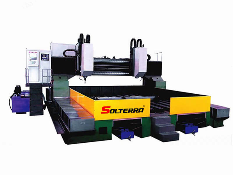
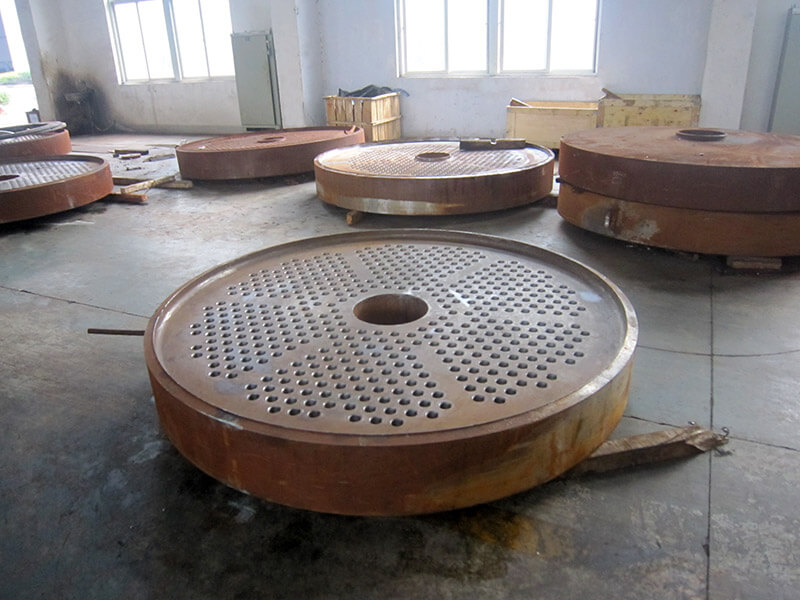
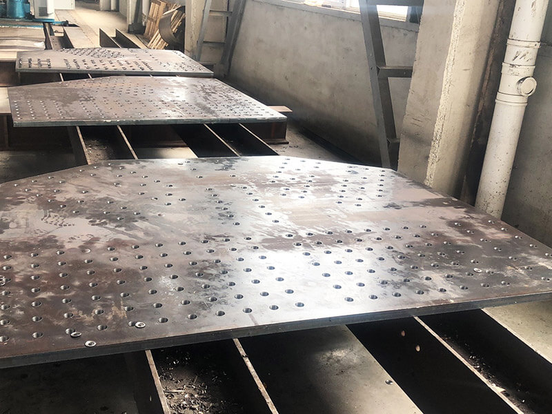
This series machine is used for the drilling processing for tube plate, clapboard and flange, in petrochemical, boiler, and wind power flange industries, also for joint plates in building, bridge, iron tower, etc.
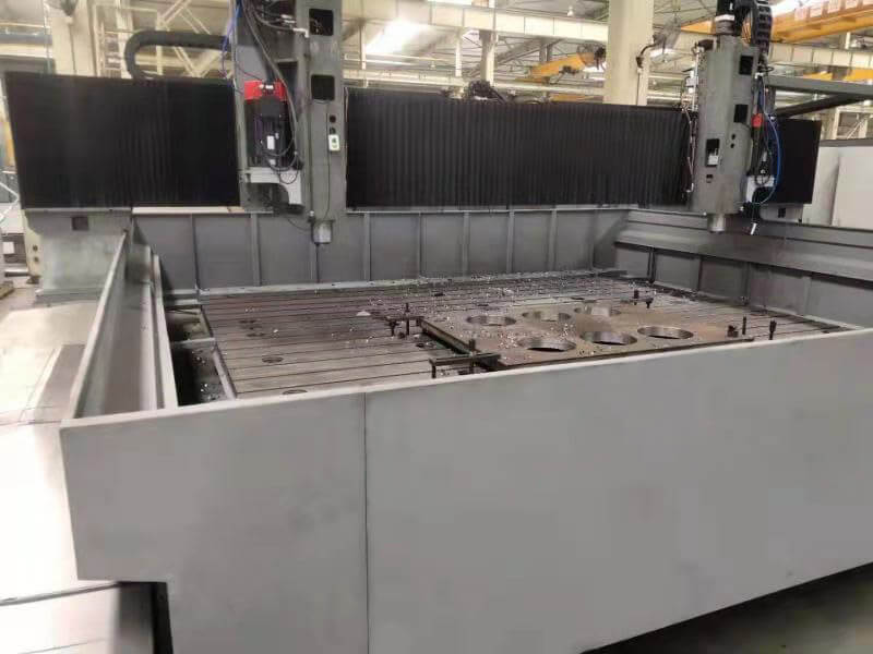
1. Heavy-load linear roller guide pairs are equipped on two sides of the machine bed respectively. The longitudinal movement of the gantry's two sides is driven synchronously via AC servo motor and precise ballscrew pair of big pitch.
2. Two movable slides are equipped on the cross beam of gantry. The sliders are guided by two linear roller guide pairs and driven by AC servo motor and precise ballscrew pair of big pitch respectively.
3. The slides on the cross beam are equipped with vertical CNC feeding ram-type drilling spindle, which adopts special conversion motor with heavy load for spindle. The motor drives the spindle via synchronous belt. The drilling spindle adopts Taiwan precision spindle (innercooling) with disk spring automatic broach mechanism, hydraulic cylinder loosing cutter, very convenient to change shank.
4. The machine is equipped with hydraulic system to finish the hydraulic balance of vertical ram and hydraulic cutter loosing of spindle.
5. It adopts Germany Siemens CNC system, equipped with RS232 interface and LCD screen. The automatic programming provided can not only generate processing programs automatically, but also preview hole position before drilling.
6. It is equipped with chain-plate type automatic chip-conveyor and chip collection trolley. The cooling system is equipped with high-pressure innercooling pump and low-pressure outercooling pump, which are used for innercooling or outercooling of cutter.
| Model | PHD2020 | PHD3030 | PHD4040 | |
| Max. size of workpiece (mm) | Max. hole distance L×W (mm) | 2000x2000 | 3000x3000 | 4000x4000 |
| Max. thickness (mm) | 200 | |||
| Worktable | Width/distance of T groove (mm) | 28/500 | ||
| Drilling spindle | Quantity | 2 | ||
| Spindle taper | BT50 | |||
| Max. diameter of drilling (mm) | Φ40 (carbide drill) Φ50 (high speed twist drill) | |||
| Rotation speed(stepless) (r/min) | 30~3000 | |||
| Motor power of spindles (kW) | 2×18.5 | |||
| Spindle nether surface to work table (mm) | 200~700 | |||
| (X axis) Longitudinal movement of gantry | Max. stroke (mm) | 2000 | 3000 | 4000 |
| X axis feeding speed (m/min) | 0~7 | |||
| X axis servo motor power (kW) | 2×3 | |||
| (Y axis) Horizontal move | Max. distance of spindles (mm) | 2000 | 3000 | 4000 |
| Y axis feeding speed (m/min) | 0~7 | |||
| Y axis servo motor power (kW) | 2×3 | |||
| (Z axis) Vertical move | Z axis Max. stroke (mm) | 500 | ||
| Z axis feeding speed (m/min) | 0-5 | |||
| Z axis servo motor power (kW) | 2×3 | |||
| Positioning precision | X,Yaxis | ≤0.1/ (full length) | ||
| Re-positioning precision | X,Yaxis | ≤0.05 | ||
| Hydraulic system | Hydraulic pump (Mpa)/ (L/min) | 7 /25 | ||
| Motor for hydraulic pump (kW) | 3 | |||
| Chip removal and cooling | Type of chip-conveyor | Chain-plate type | ||
| Quantity of chip-conveyor | 1 | |||
| Chip-removal speed (m/min) | 1 | |||
| >Motor for swarf conveyor (kW) | 0.75 | |||
| Motor for cooling pump (kW) | 2×3+0.75 | |||


